Changes since last post
 |
| A failed part where the steel ring moved out of position due to viscous forces. |
 |
| A void with burning that SolidWorks failed to predict. |
The main lesson we learned from optimizing our process is that it's really hard to predict how plastic will flow while molding or forming. SolidWorks didn't predict any of the air traps we observed, and we estimated the shrinkage wrong for each of our four parts. The takeaway is: produce molds early, test them, and see what happens in reality!
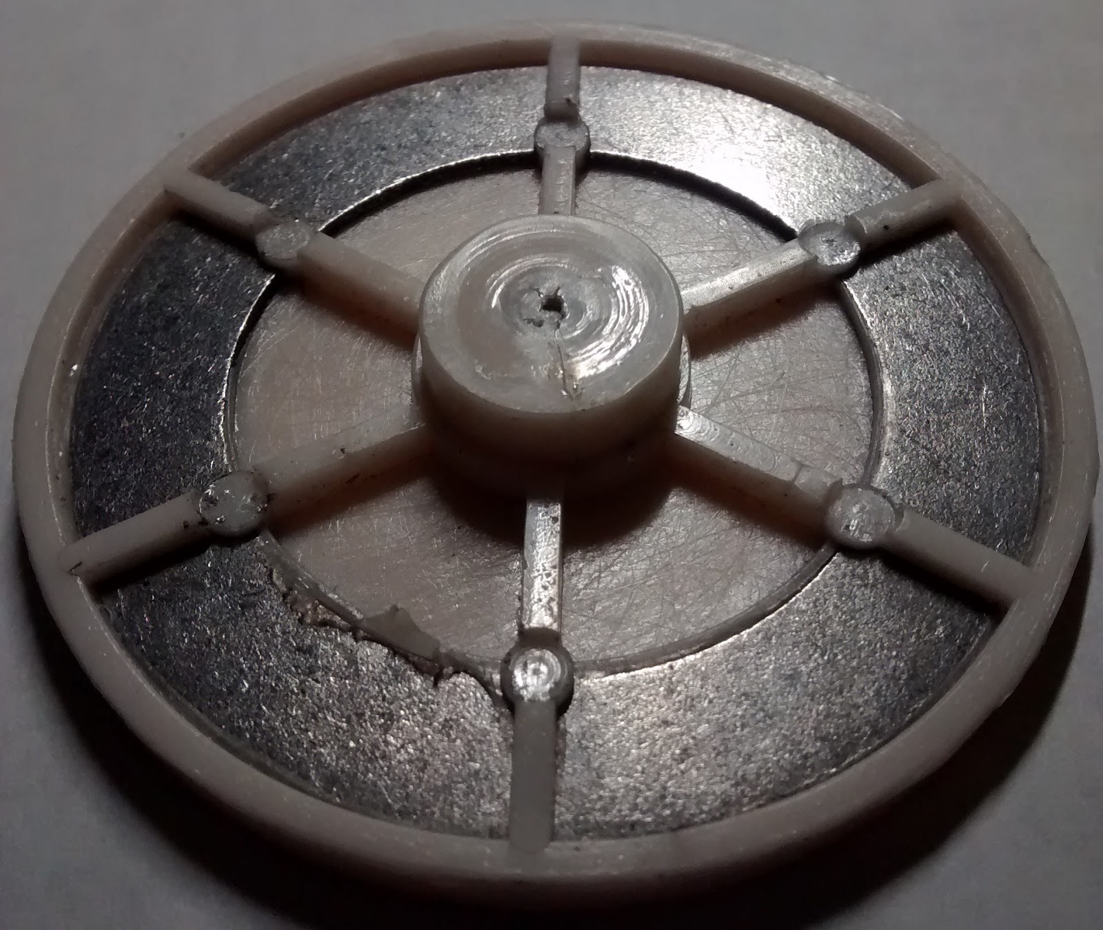 |
| The inner face of the yoyo, with an embedded (insert molded) steel shim that drastically reduced shrinkage. |
Another interesting lesson we learned is that embedding steel within a plastic part dramatically reduces shrinkage. Recall that the coefficient of thermal expansion for polypropylene is more than 10x larger than the coefficient of thermal expansion for steel, and steel is much stiffer than polypropylene. So when you put a steel shim into a part, that steel reinforcement will significantly reduce the shrinkage of the part as it cools.
Another little lesson we learned is that process parameters usually produce a range of shrinkages about 0.2% wide. Of course, geometry will have the biggest effect on shrinkage, but you can wiggle it a little bit just by changing your process parameters.
Perfecting the body hemisphere
About the molds
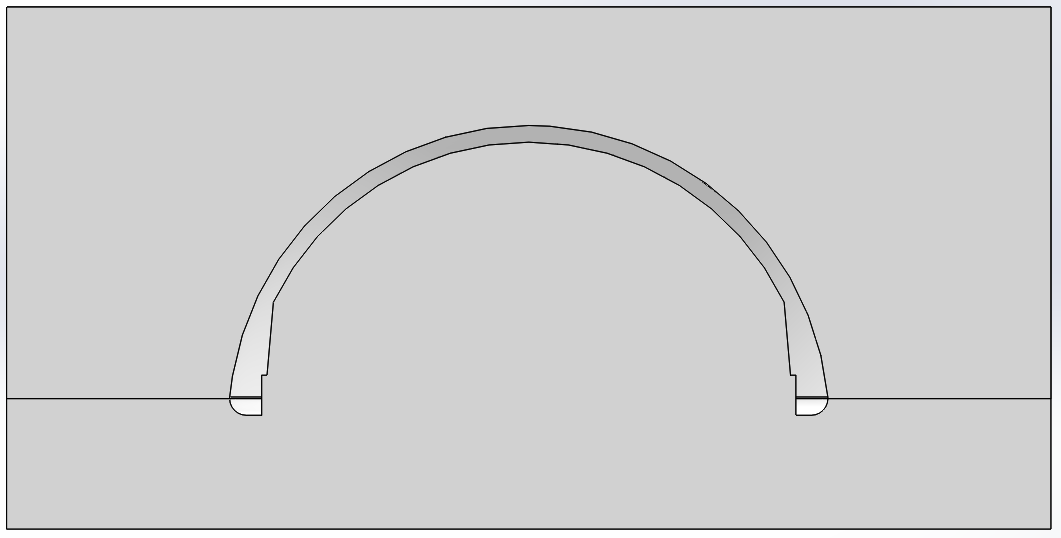 |
| A cross section of the two-part mold for the body hemisphere. |
The mold for the body hemisphere is a pretty standard two-part mold. One part is the cavity side, which defines the outer dome surface, and the other side is the core side, which defines the inner dome surface and the ring that presses onto the inner face part. The parting line for the molds was chosen to be exactly where the outer surface is perpendicular to the parting direction, so that the part wouldn’t get stuck in either mold.
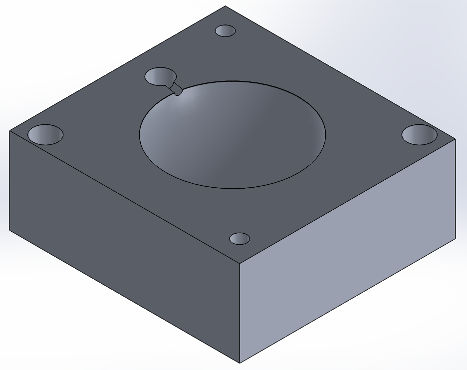 |
| A CAD model of the cavity mold for the body hemisphere. |
The cavity mold is just a large dome, which I sanded as smooth as possible because it’s the surface that the user will touch most often. There’s a sprue hole which allows plastic to flow in from the nozzle and through the gate channel; this hole is tapered so that the plastic will separate easily.
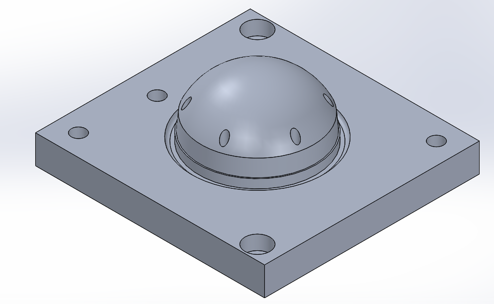 |
| A CAD model of the core mold for the body hemisphere. |
Cutting the molds
Since the part itself was more than an inch tall, we chose to use the 1.5” mold blanks so we’d have plenty of material. Fortunately, the part was almost rotationally symmetric, so almost all the machining could be done quickly on the CNC lathe.
 |
| The finished cavity mold part. |
The cavity mold is just a simple dome, so I started with a simple MasterCAM program using tool #1. Even though the simulation said everything was fine, the rear back side of the tool holder actually collided with the part and ruined the bottom of the dome; the lesson I learned was a good simulation doesn’t mean it will work. To resolve the issue, I switched to using tool #3, which has a much smaller tool holder, but leaves rougher grooves because it’s sharper.
The process plan used for the cutting the cavity mold.
Step
|
Operation
|
Machine
|
Tool
|
Justification
|
1
|
Rough dome
|
Daewoo
|
#3
|
Remove material to form the hemisphere
|
2
|
Finish dome
|
Daewoo
|
#3
|
Accurately smooth out the surface of the hemisphere
|
3
|
Mill runner
|
Prototrak
|
#9
|
Cut a groove for a runner from the gate to the part
|
4
|
Sand dome
|
600 grit sandpaper
|
Make the user-facing surface very smooth
|
 |
| The finished core mold part. |
The core mold is much more complex. I started by drilling the ejector pin holes on the mill, and then reaming them out. Then, I put the blank in the lathe, and used tool #1 to rough and finish the dome, which gave a nice smooth finish. Then, I used the trepanning tools to cut the groove at the base of the part, and finish the press-fit diameter.
The process plan used for the cutting the core mold.
Step
|
Operation
|
Machine
|
Tool
|
Justification
|
1
|
Center drill ejector pin holes
|
Prototrak
|
#13
|
Accurately locate holes for ejector pins
|
2
|
Drill ejector pin holes
|
Prototrak
|
#17
|
Remove material for the ejector pins
|
3
|
Ream ejector pin holes
|
Drill press
|
.126” reamer
|
Make holes smooth for sliding fit
|
4
|
Rough dome
|
Daewoo
|
#1
|
Remove material to form the hemisphere
|
5
|
Finish dome
|
Daewoo
|
#1
|
Accurately smooth out the surface of the hemisphere
|
6
|
Finish dome-groove corner
|
Daewoo
|
#3
|
Use a sharp tool to make a nice corner
|
7
|
Cut groove
|
Daewoo
|
#9
|
Remove material in the groove that tool #1 could not reach
|
8
|
Finish press fit diameter
|
Daewoo
|
#7
|
Finish turning the press fit diameter with a smaller radius than tool #9
|
Optimizing the injection process
Finally, time to optimize the process parameters. At this point, I had already made the dome thicker to eliminate an air trap, and recut the press-fit diameter to meet the specification, so the only issue left was to consistently hit the critical dimension.
Since I wanted to affect shrinkage, I focused on varying the injection hold pressure and cooling time. After attempting a couple of parts with varying parameters, I compiled the below list to decide on which were the best parameters.
To give myself a little margin for error on either side, I chose to use the parameters which gave a diameter of 1.997; this meant higher injection hold pressure and longer cooling time.
A table of parameter variations tested, and the resulting dimensions.
Part numbers
|
Initial holding pressure (psi)
|
Cooling time (sec)
|
Average Critical diameter (in)
|
Flash
|
Weld lines
|
Warping
|
Target
|
Shortest
|
1.995
|
None
|
None
|
None
| |
14,15
|
600
|
10
|
1.992
|
Slight edge
|
Barely visible
|
Barely noticeable
|
16,17
|
1000
|
10
|
1.993
|
Slight edge
|
Barely visible
|
Barely noticeable
|
18,19
|
1000
|
15
|
1.997
|
Slight edge
|
Barely visible
|
Barely noticeable
|
20,21
|
600
|
15
|
1.995
|
Slight edge
|
Barely visible
|
Barely noticeable
|
To give myself a little margin for error on either side, I chose to use the parameters which gave a diameter of 1.997; this meant higher injection hold pressure and longer cooling time.
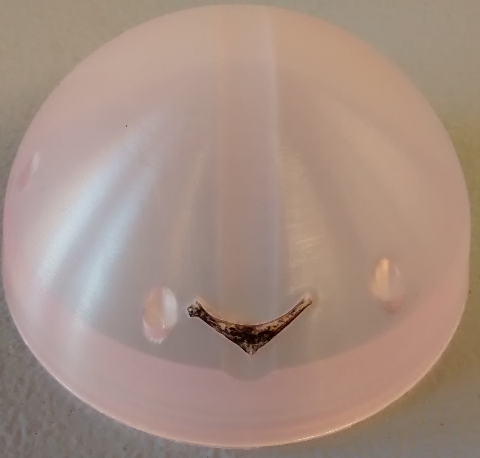
| Part 19, with slight defect highlighted. |
The parameters that produced part 19.
Injection hold pressure profile (psi)
|
| ||||||||||
Injection hold time (sec)
|
6
| ||||||||||
Cooling time (sec)
|
15
| ||||||||||
Set screw feed stroke (in)
|
1.6
| ||||||||||
Injection speed profile (in/s)
|
| ||||||||||
Injection boost pressure (psi)
|
1600
| ||||||||||
Intrusion time (sec)
|
Not needed
| ||||||||||
Intrusion speed (in/s)
|
Not needed
| ||||||||||
Screw feed delay time (sec)
|
2
| ||||||||||
Ejector counter (counts)
|
3
| ||||||||||
⅛” ejector pins
|
6X 5.640” pins
| ||||||||||
Total shim thickness (in)
|
0
| ||||||||||
¼” ejector pin
|
II (second shortest)
|